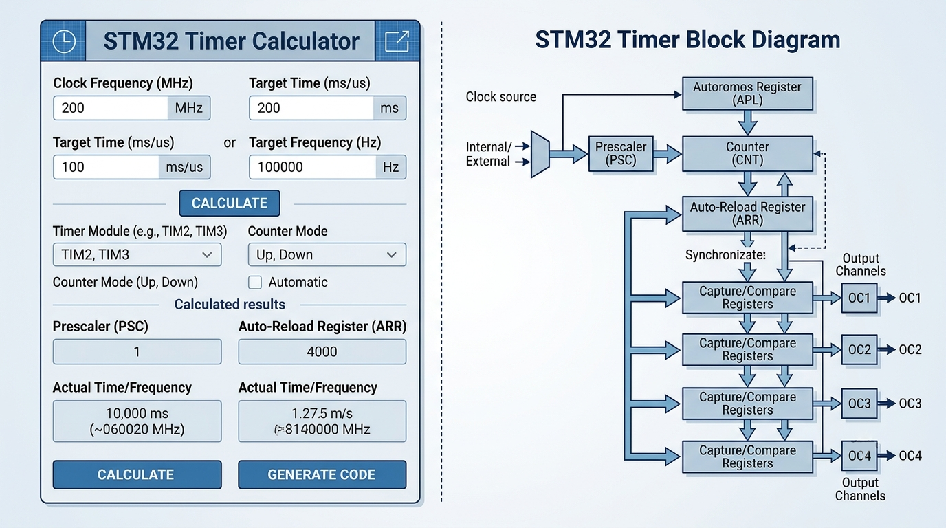
STM32 Timer Calculator Tool Introduction
Configuring timers on STM32 microcontrollers can be confusing, especially for beginners. With PSC, ARR, and CCR values to figure out, finding the right numbers takes time – and a wrong calculation can break your project....
Calculate STM32 Timer Settings in Seconds with the Timer Calculator
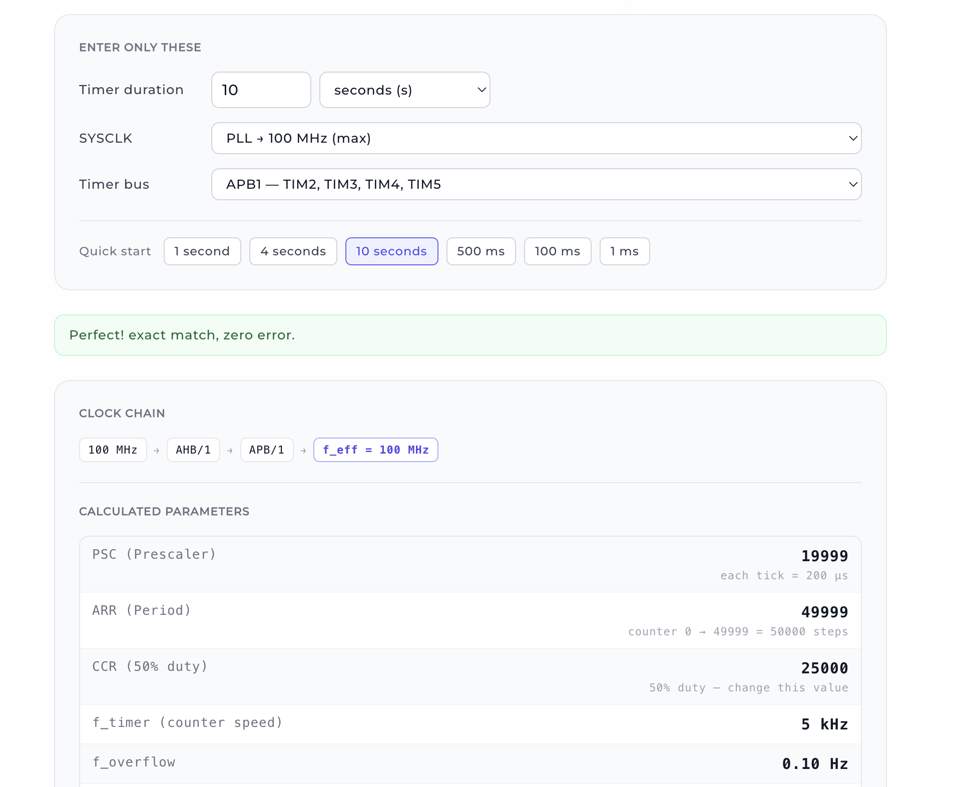
Configuring timers on STM32 microcontrollers can be confusing, especially for beginners. With PSC, ARR, and CCR values to figure out, finding the right numbers takes time – and a wrong calculation can break your project or cause unexpected behaviour. That’s exactly where the STM32 Timer Calculator comes to the rescue. All you need to do is enter the desired time; the tool automatically computes PSC, ARR, and even CCR values, analyses the clock tree, shows the error rate, and generates ready-to-use C code. In this post, I’ll explain how this tool saves you time and in which situations you’ll find it most useful.
What Does This Tool Do?
STM32‑based projects often use timers for PWM generation, servo motor control, ultrasonic distance measurement, ADC triggering, stepper motor driving, or generating periodic interrupts. Each application requires correct PSC and ARR values. This tool automatically calculates the clock tree (SYSCLK → AHB → APB → Timer), applies the rule that timer clock doubles when APB prescaler > 1, and finds the optimal PSC/ARR combination with the lowest possible error. The formulas work for STM32F1, F2, F3, F4, and L4 series.
How to Use It
Using the tool is straightforward:
1. Enter the timer duration (e.g., 4 seconds).
2. Select the system clock (SYSCLK) – HSI, HSE, or PLL multiplied.
3. Choose the APB bus the timer is connected to (APB1 or APB2).
4. Click "Calculate".
The tool instantly gives you:
- PSC (Prescaler) value
- ARR (Period) value
- CCR (optional for duty cycle)
- Actual period and error rate
- Clock tree analysis
- Ready‑to‑use C code (SystemClock_Config and MX_TIM_Init functions)
- LED behaviour simulation (example with PC13)
Quick‑start presets (1s, 4s, 10s, 500ms, 100ms, 1ms) are also available.
Example C code generated by the tool (timer initialisation and LED control)
void SystemClock_Config(void)
{
  RCC_OscInitTypeDef RCC_OscInitStruct = {0};
  RCC_ClkInitTypeDef RCC_ClkInitStruct = {0};
  __HAL_RCC_PWR_CLK_ENABLE();
  __HAL_PWR_VOLTAGESCALING_CONFIG(PWR_REGULATOR_VOLTAGE_SCALE1);

  RCC_OscInitStruct.OscillatorType      = RCC_OSCILLATORTYPE_HSI;
  RCC_OscInitStruct.HSIState            = RCC_HSI_ON;
  RCC_OscInitStruct.HSICalibrationValue = RCC_HSICALIBRATION_DEFAULT;
  RCC_OscInitStruct.PLL.PLLState        = RCC_PLL_NONE;
  if (HAL_RCC_OscConfig(&RCC_OscInitStruct) != HAL_OK) { Error_Handler(); }

  RCC_ClkInitStruct.ClockType      = RCC_CLOCKTYPE_HCLK|RCC_CLOCKTYPE_SYSCLK
                                   |RCC_CLOCKTYPE_PCLK1|RCC_CLOCKTYPE_PCLK2;
  RCC_ClkInitStruct.SYSCLKSource   = RCC_SYSCLKSOURCE_HSI;
  RCC_ClkInitStruct.AHBCLKDivider  = RCC_SYSCLK_DIV1;
  RCC_ClkInitStruct.APB1CLKDivider = RCC_HCLK_DIV1;  // TIM2 effective = 16 MHz
  RCC_ClkInitStruct.APB2CLKDivider = RCC_HCLK_DIV1;
  if (HAL_RCC_ClockConfig(&RCC_ClkInitStruct, FLASH_LATENCY_0) != HAL_OK) { Error_Handler(); }
}

static void MX_TIM2_Init(void)
{
  TIM_ClockConfigTypeDef sClockSourceConfig = {0};
  TIM_MasterConfigTypeDef sMasterConfig = {0};

  htim2.Instance               = TIM2;
  htim2.Init.Prescaler         = 1279;     // 16 MHz / (1279+1) = 12.5 kHz
  htim2.Init.CounterMode       = TIM_COUNTERMODE_UP;
  htim2.Init.Period            = 49999;    // counter 0..49999 = 50000 steps → 4 sec
  htim2.Init.ClockDivision     = TIM_CLOCKDIVISION_DIV1;
  htim2.Init.AutoReloadPreload = TIM_AUTORELOAD_PRELOAD_DISABLE;
  if (HAL_TIM_Base_Init(&htim2) != HAL_OK) { Error_Handler(); }

  sClockSourceConfig.ClockSource = TIM_CLOCKSOURCE_INTERNAL;
  HAL_TIM_ConfigClockSource(&htim2, &sClockSourceConfig);
  HAL_TIMEx_MasterConfigSynchronization(&htim2, &sMasterConfig);
}

// LED control inside while(1)
uint32_t counter;
HAL_TIM_Base_Start(&htim2);
while (1) {
  counter = __HAL_TIM_GET_COUNTER(&htim2);
  if (counter < 25000) HAL_GPIO_WritePin(GPIOC, GPIO_PIN_13, GPIO_PIN_RESET); // ON
  else                 HAL_GPIO_WritePin(GPIOC, GPIO_PIN_13, GPIO_PIN_SET);   // OFF
}
"The STM32 Timer Calculator takes the headache out of PSC and ARR calculations, letting engineers focus on creativity."
When Should You Use It?
- PWM signal generation (motor drivers, LED dimming, servo control)
- Ultrasonic sensor (HC-SR04) trigger and echo timing
- Periodic ADC conversions
- Generating interrupts for task scheduling
- Stepper motor speed and step control
- Timeout settings for various operations
Basic Formulas
The tool uses these formulas behind the scenes:
- f_timer = f_APB_eff / (PSC + 1)
(if APB prescaler > 1, f_APB_eff = f_APB × 2)
- f_overflow = f_timer / (ARR + 1)
- Duty (%) = CCR / (ARR + 1) × 100
Instead of playing with these manually, let the tool give you instant, accurate results.
FAQ
Which STM32 series does the tool support?
It works with STM32F1, F2, F3, F4, L4, and any series with a similar timer architecture.
Does the tool account for APB prescaler changes?
Yes! It automatically calculates the effective timer clock based on the selected APB bus and its prescaler setting.
Can I use it for PWM duty cycle, not just timing?
Absolutely. Enter the desired CCR value and the tool computes the duty cycle. It also provides a simple LED simulation.
Why is the error rate important?
For applications that demand precise timing (e.g., audio synthesis, accurate measurements), a low error rate is essential. The tool finds the PSC/ARR pair that minimises error.
Where can I access this tool?
You can use it directly via the link below.
Conclusion
The STM32 Timer Calculator is an indispensable companion for developers who frequently struggle with timer configuration or lose valuable time on manual calculations. By automatically analysing the clock tree, showing error margins, and generating production‑ready C code, it accelerates both learning and productivity. Use it often in your STM32 projects to make timers work for you, not against you.